by

Geopipe

Before knowing what a geopipe or geosynthetic pipeline is, it helps us to know the types of geosynthetics and their understanding, from several articles on the internet or Google or also on Wikipedia. I summarize some of them as follows:


Geosynthetic Types and their Definition


Geosynthetic is a type of synthetic material / synthetic material used to improve soil and road construction that has unstable soil and surface contours. There are many types of geosynthetics that are often used for making road layers and soil which are often used for road construction.
Geosynthetic Types and Definition:
1. Geobag is geotextile that is filled with soil and sewn so that it forms padding which is used to replace conventional coastal protection rocks / buildings.
2. Geocomposite is a composite material made from non woven geotextile base material with woven high-strength 2-way polyester yarn. Thus we get two functions at once namely strengthening and separation as well as the filtration function.
3. Geogrid is a type of Geosynthetic material (Geosynthetic) which has a large enough opening, and body stiffness that is better than Geotextile. Geogrid basic materials can be: Polyphropylene, Polyethilene and Polyesther or other polymer materials.
4. Geomembrane is plastic sheet made from HDPE / LLDPE / PVC, etc. This sheet is made using sophisticated and modern machinery so that its specific gravity and thickness are maintained. Geomembrane has characteristics that are impermeable to liquids.
5. Geopipe is a perforated or solid polymer pipe that is used to drain liquids, gases and includes leachates or gas collectors in landfill applications.
6. Geotextile is one of the translucent Geosynthetics (Geosynthetic) materials, which can be used / functions as a separator, filter, protection, and reinforcement. The basic ingredients are Polyesther or Polyprophilene. Generally divided into two types: Non Woven and Woven.
The use of geosynthetics or synthetic materials is related to the durability of synthetic materials in chemical compounds, weathering, wear, ultraviolet light and microorganisms. The most important polymers that are used for geosynthetic manufacturing are Polyester (PET), Polyamide (PM), Polypropylene (PP), and Polyethylene (PE).
Article source:
from the author: Samsul Arifin
Article title: Geosynthetic Types and Definition
academia.edu

Related to the products manufactured by PT. Shuanglin Pipe Indonesia namely geosynthetic pipe or goepipe. Here is information about what is a goepipe or geosynthetic pipe.


What is Geopipe?


Geopipe Corrugated Perforated atau Non Perforated merupakan pipa HDPE bergelombang dan berlubang atau tidak berlubang yang digunakan sebagai “subdrain system” pada lapangan sepak bola, lapangan golf, taman dll atau sebagai pipa saluran pembuangan atau selongsong pipa kabel bawah tanah.

Geopipe didesain agar dapat menahan beban tekanan lebih baik dibandingkan pipa jenis biasa, memiliki panjang hingga 50 meter dengan berat yang ringan sehingga memudahkan dalam proses mobilisasi di lapangan.

Tipe Geopipe terdapat 2 jenis yaitu single wall dengan bagian luar dan dalamnya bergelombang dan double wall dengan bagian dalamnya mempunyai lapisan tambahan.

DN : Nominal Diameter/br>
OD : Outside Diameter

*All unit measurement base on (mm)


Geopipe is all plastic pipes used in soil, rock, or other subsurface materials as an integrated part of a project, structure or system.


Benefits:

  • Quick Installation
  • Having strength at good pressure
  • Easy handling
  • Efficient drainage
  • Flexible
  • Corrosion resistant
  • Large drainage capacity

Application:

  • Subsurface drainage in road construction
  • Drainage in residential and commercial construction
  • Drainage at the mine
  • Agricultural land
  • Building foundation
  • Retaining wall application
  • Construction land
  • Sports field and recreation area
by

HDPE/PE pipe introduction

HDPE pipe is a type of flexible plastic pipe used for fluid and gas transfer and is often used to replace ageing concrete or steel mains pipelines. Made from the thermoplastic HDPE (high-density polyethylene), its high level of impermeability and strong molecular bond make it suitable for high pressure pipelines. HDPE pipe is used across the globe for applications such as water mains, gas mains,[1][self-published source?] sewer mains, slurry transfer lines, rural irrigation, fire system supply lines, electrical and communications conduit, and stormwater and drainage pipes.


Benefits


The toughness and resistance to chemicals of polyethylene, as well as the corrosion resistance and low weight have contributed to its growing use in situations where cost-effective and durable fluid and gas piping systems are required. According to a press release from the Plastics Pipe Institute, “PE piping has been used for water and other fluids in Europe and America since the 1950s due to its durability, leak free joints, resistance to corrosion, and long-term cost-effectiveness.”

HDPE pipe can be joined by butt weldingelectrofusion welding, socket welding, or extrusion welding. These joints heat the pipe during the joining process, creating a completely homogenous joint so the weld becomes as strong, or stronger than the existing pipe on either side of the weld. There is no need to use rubber seals or jointing chemicals, as is used for joining PVC pipe, which cause environmental health issues and increase the chance of failure over time. PE is less likely to have problems with root intrusion, and provides integrity for the pipeline, even when installed in unstable soils.

Due to the fusion welded system, the need for anchors or thrust restraint blocks are eliminated, as the joints become fully end load resistant, reducing costs for material and installation time. This also allows for safer excavation close to the pipeline in future, which is particularly important for high pressure gas pipelines. Coils of PE Pipe make trench-less installation safer and less intrusive on the surrounding environment.

HDPE Pipe Systems are available for many applications, providing for standard trenching of water mains, fire ring mains, sewer mains, and gas mains pipelines, as well as horizontal drilling for electrical and telecommunications conduits.[3] According to a company that manufactures HDPE, HDPE systems are cost-effective to install and have long-term maintenance cost savings, and also allow for cheaper installation methods, such as HDD (horizontal directional drilling), slipliningpipe bursting, floating and submerged pipe.

HDPE pipe is very durable and flexible and can be bent on site to a radius twenty-five times the nominal pipe diameter – for SDR11 and SDR17 pipe, at or below 20°C ambient temperature. This provides major cost savings, when compared to different pipe systems, some of which require glued fittings, restraints or thrust blocks for even minor changes in direction. Because of the high impact resistance and flexibility of HDPE pipe, it is well suited to installation in dynamic soils including in earthquake-prone areas. HDPE pipe has very high flow capacity, because of its smooth bore and end-to-end jointing methods. HDPE pipe does not corrode in the environment, and will maintain its flow capabilities over time, unlike ferrous piping systems, which will rust and build up internal resistance to fluid flowing through it.

Because food-grade polyethylene virgin material is used to fabricate HDPE pipes, they are safe for the transfer of potable water, provided that any initial debris has been flushed out. HDPE pipe is resistant to many chemicals, facilitating its use in process plants or around corrosive or acidic environments, without needing to use protective coatings or galvanising, as is required on steel pipes. As HDPE has a very low thermal conductivity, it can maintain more uniform temperatures compared to metal pipes, when carrying fluids, which will greatly reduce any need for insulation to control condensation around the pipeline.


Manufacture


To make pipe lengths, HDPE resin is heated and extruded through a die, which determines the diameter of the pipeline. The wall thickness of the pipe is determined by a combination of the size of the die, speed of the screw and the speed of the haul-off tractor. Polyethylene pipe is usually black in color due to the addition of 3-5% of carbon black being added to the clear polyethylene material. The addition of carbon black creates a product which is UV resistant. Other colours are available but are less common. Coloured or striped HDPE pipe is usually 90-95% black material, with just a coloured skin or stripe on the outside 5%.

The following shows the process for HDPE Pipe Extrusion:

Piping Systems - Extruded 800mm HDPE Pipe

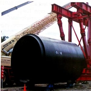
Freshly Extruded 800 mm (31.50 in) HDPE Pipe

Polyethylene raw material is pulled from a silo, into the hopper dryer, which removes any moisture from the pellets. Then it is pulled by a vacuum pump into the blender, where it is heated by a barrel heater. The PE material becomes molten at around 180 °C (356 °F), allowing it to be fed through a mould/die, which shapes the molten material into a circular shape. After coming through the die, the newly formed pipe quickly enters the cooling tanks, which submerge or spray water at the pipe exterior, each one reducing the temperature of the pipe by 10-20 degrees. Because polyethylene has a high specific heat capacity, the pipe must be cooled in stages, to avoid deforming the shape, and by the time it reaches the “haul-off tractor,” it is hard enough to be gently pulled by the 2-3 belts. A digital or powder printer, the size, type, date and manufacturers name is printed on the side of the pipe. It is then cut by a saw cutter, either into lengths of 3 or 6 or 12 or 24 meters (9.8 or 19.7 or 39.4 or 78.7 ft), or it is coiled to 50 or 100 or 200 m (164 or 328 or 656 ft) lengths on a coiler.

A different die is used for striped HDPE pipe, which has small channels that the coloured material runs through, just before it is pushed through the die. This means the stripes are formed as an integral part of the pipe and are not likely to separate from the main pipe body. Co-extruded, or co-ex HDPE pipe, has a second extrusion screw which adds an extra skin of colour around the black HDPE pipe, this allows the pipe to be coloured on the outside, for identification or thermal cooling requirements.


Uses


An example of the durability of HDPE pipe is the 600 m (1,969 ft) long HDPE boom used for the Ocean Cleanup project. The HDPE pipeline is being released into the ocean to clean up the Great Pacific Garbage Patch.

HDPE pipe has been used in rural and mining environments in Australia for over 50 years, proving to be a very durable and effective means of fluid and gas transfer.


Life expectancy


Although HDPE pipe is often estimated to last 50 years, they are in fact more likely to have life expectancies of 100 years. PIPA (Plastics Industry Pipe Association) and the Plastic Pipe Institute (PPI) have written technical white papers on HDPE design life. The PIPA paper is called “Life Expectancy for Plastics Pipes” which mentions that because of the fifty-year stress regression data, people[who?] falsely assume that plastic pipe systems’ life expectancy is only fifty years. In fact, these pipe systems can be reasonably expected to last up to or more than 100 years.

In Germany, PE pipes and PE fittings were introduced during the mid-1900s, mainly for irrigation or water supply, but also for gas, fuel, and other industrial applications. The use of this 50-year time interval, leads to a misunderstanding that it represents a 50-year pipe life. For pipe systems that have been correctly manufactured and installed, the actual life cannot be predicted, but can be expected to be over 100 years until major rehabilitation is needed.


References


  1.  “PIPA Technical Paper on Polyethylene used for Gas Pipe Material” (PDF).
  2. ^ “Plastics Pipe Institute study confirms long life expectancy for polyethylene pipe in municipal water systems” (PDF).
  3. ^ “Article about the growth of HDPE Conduit systems, and their advantages over PVC Pipe”. September 2009.
  4. ^ “Benefits of HDPE Pipe”.
  5. Jump up to:a b c “PIPA Technical Whitepaper on ‘Life Expectancy for Plastics Pipes (PDF). Plastics Industry Pipe Association of Australia Ltd.
  6. ^ “Research on Above-ground applications for PE Pipe” (PDF).
  7. ^ “AGRU and The Ocean Cleanup”www.agru.at. agru Kunststofftechnik Gesellschaft m.b.H. Retrieved 16 September 2019.
  8. ^ “PIPA Technical Commentary on Polyethylene pipes for pressure applications” (PDF).


resource from https://en.wikipedia.org/wiki/HDPE_pipe

by

Handbook Plastic Pipe Ringstiffness 5

Determination of the deformation of the segment

The segment is deformed to an extent as it would be during a deformation of the whole pipe of 3%. The deformation of the segment is calculated according to the following equation:


YRS = YS X α79O = 0.03 X di x 0.29

YRS = deformation of pipe segment (mm), which corresponds to a pipe-deformation of 3%

YS = the vertical deformation of the pipe (mm), which corresponds to a pipe-deformation of 3%

α79 = conversation factor for deformation of 79o segment = 0.296 (devired analytically)


Calculating the ring stiffness

The ring stiffness S of each test body can be calculated with the formula

S          = (0.0186+0.025xYs/di)xF79α/(LxYs)

F79a      = test force when deformation of pipe segment YRS is achieved (kN)

Ys        = vertical deformation of the pipe (m)

di            = inner diameter of pipe segment (m)

L          = length of pipe segment (m)

by

Handbook Plastic Pipe Ring Stiffness part 4

3.1 Determination of ring stiffness under use of pipe segments

In the following abstract the most important details of the procedure acc.
GIN 16917 are explained.

A mathematic investigation has proven that there exists a relationship between testing 79° pipe segments and the standard test procedure according to DIN EN ISO 9969. The same ring stiffness can be calculated. However, it is recommendable to also apply other testing procedures under prevailing working conditions and profile types before this alternative method is exclusively taken. A comparison and evaluation of the result of both methods is recommended.

The ring stiffness test acc. DIN 16917 is carried out with 79° segments, extracted from one pipe. The procedure correlates with DIN EN ISO 9969 in terms of setup and implementation and simply uses another test body. Instead of using a complete pipe, pipe segments are used. References on testing equipment, test body width, conditioning and implementation can be viewed in DIN EN ISO 9969. The cutting of the support surfaces of the segments must be carried out with special care because the bearing must be rigidly supported. Another crucial point, which should be treated with special care, is plane parallelism.

The ring stiffness is defined by measuring of strength and deformation under a constant deformation rate. Therefore, a pipe segment is used instead on a complete pipe. The pipe segment is deformed vertically under a constant rate. The deformation of a segment corresponds to the amount of deformation of a complete pipe (3%).

The test body (79° pipe segment) is pressed together at a constant speed acc. Specification of the standard ISO 9969. The measuring values of force and deformation has to be recorded continuously until a deformation corresponding to a deformation of the complete pipe of 0.03di is reached.


by

Handbook Plastic Pipe Ring Stiffness part 3

  1. Alternative Test Procedures for Ring Stiffness


All Manufacturers of large diameter plastic pipes face the same challenge regarding regular testing of ring stiffness. Especially dimensions bigger than DN 2000 are problematic, because of typical existing infrastructure in laboratories. The weight of the cut pipe lenght and the size it self require special equipment to handle the samples and more that that often bigger laboratories are necessary.


In earlier times thermoplastic pipes did not reach sizes and weights as they do today. Pipe weights of more than 2 ton/m are now realistic. The mentioned practical reasons but also commercial reasons were the beginning for developing an alternative test method for testing pipe stiffness. Furthermore the bigger the pipes the more complicate become the testing of samples by external laboratories and third party control.


Thermoplastic pipes are homogenously manufactured and provide uniform static properties around the circumference and lenght. A cut pipe segment should have same characteristics if the disturbing load differences are considered. A group of large diameter pipe producers made many tests to verify the theoretical assumptions and in the meantime in the Germen DIN 16917 the procedure is described in detail.


by

Handbook Plastic Pipe Ring Stiffness part 2

2. Standard Ring Stiffness Test Procedures

Mainly we differ two different procedures to measure and evaluate the pipe-stiffness:
a. Testing under constant load
acc. DIN 16961-2: Thermoplastic pipes with profiled wall and smooth pipe inside
b.Testing under constant speed
acc. DIN EN ISO 9969: Thermoplastic Pipes-determination of Ring stiffness

At noth procedures a cut length of pipe (typically up to 1 m long) is being horizontal supported and compressed vertically between two parallel flat plates.


2.a Constant load

Testing under constant load goes back to the early standard of DIN 16961, where the procedure until now is standardized. Typically the Test takes 24 hours and a 24h value for stiffness is defined = SR24 but also long-term tests up to 2000 or 10000 hours are applicable.

The steeps of the test procedure can be summarized as follows:

  1. Geometical analysis of the used wall structure
  2. Calculating the theoretical pipe stiffness under consideration of results for geometrical analyses and Ec modulus for the expected testing-time
  3. Calculation the test-load (weight) under consideration of chosen theoretical deflection (typical 3%)
  4. Beginning Test by loading the pipe crown with calculated weight
  5. Measuring deflection during testing time
  6. Result for deflection has to be equal or lower than theoretical deflection


2.b Constant speed

Testing under constant speed is standardized in DIN EN ISO 9969 and it is mainly a short-term test.
The ring stiffness is determined by measuring the force and the deflection while deflecting the pipe at a constant deflection speed. The ring stiffness is calculated as a function of the force necessary to produce a 3% diametric deflection of the pipe.
The deflection speed depends on the nominal diameter of the pipe, for large diameters, nominal diameter >710 mm the speed is specified with as 0,03 x Inner diameter (mm/min) a tolerance of +- 5%
Typically the stiffness is categorized in classes according to the mentioned standards, SN classes = SN 2; SN4; SN8; SN16, but intermediate stiffness values are also often used for technical description: e.g. S = 7 kN/m²
Roughly the stiffness can be calculated theoretically for both procedures so far as the creep modulus E is know and also the geometrical data for moment of inertia and distance of gravity is determined.


Switch The Language
    × Contact Us!

    PT SHUANGLIN PIPE INDONESIA is a joint venture subsidiary of Zhejiang Shuanglin Environment Co., Ltd. Our factory is located in CIKARANG, Indonesia. The plant covers an area of 4,000 square meters. Our company has introduced advanced production line and a professional production management team. The company mainly produces municipal and residential building water supply and drainage, sewage pipes and complete sets of systems. The product line includes HDPE/PP double-wall corrugated pipe and inspection wells for pipeline connection and other accessories.

    ADDRESS

    KAWASAN INDUSTRI DELTA SILICON 5 JL.KENARI BLOCK G.1 NO.28A-B LIPPO CIKARANG CIBATU CIKARANG SELATAN KAB BEKASI JAWA BARAT

    ADDRESS

    PT SHUANGLIN PIPE INDONESIA
    (NEW PLANT KITIC)
    Jl. Anggrek VII, Kavling No.26 Kawasan Industri Terpadu Indonesia China (KITIC ) Deltamas, Desa Nagasari. Kec. Serang Baru. Kabupaten Bekasi. Jawa Barat 17330

    PHONE

    (021) 89915151

    EMAIL

    info@shuanglinpipe.co.id